Victron Energy LYN020102000 bus bar 1 pc(s) Acrylonitrile butadiene styrene (ABS)
Similar Products
Product Information
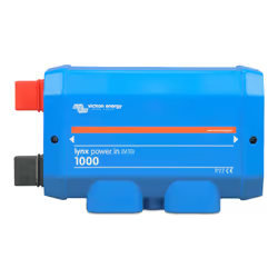
The Lynx Power In contains a positive and negative busbar with 4 connections for batteries, loads or chargers and a ground connection. It is part of the Lynx Distribution system and is available in two versions, with M8 or M10 busbar. Note that M10 refers to the busbar connection joints where the modules are connected to each other. The fuse and cable connections are always M8.
The Lynx Distribution System The Lynx Distribution System is a modular busbar system that incorporates DC connections, distribution, fusing, battery monitoring and/or Lithium battery management. For more information, see the DC Distribution Systems product page. The Lynx Distribution System consist of the following parts:
• Lynx Power In - A positive and negative busbar with four batteries or DC equipment connections, available in two versions, with M8 or M10 busbar.
• Lynx Class-T Power In - A positive and negative busbar that accepts two Class-T fuses and has two battery or DC equipment connections, available with M10 busbar.
• Lynx Distributor - A positive and negative busbar with four fused connections for batteries or DC equipment and fuse monitoring, available in two versions, with M8 or M10 busbar.
• Lynx Shunt VE.Can - A positive busbar with a space for a main system fuse and a negative busbar with a shunt for battery monitoring. It has VE.Can communication for monitoring and setup with a GX device. Available in two versions, with M8 or M10 busbar.
• Lynx Smart BMS - For use together with Victron Energy Smart Lithium batteries. It contains a positive busbar with a contactor driven by a battery management system (BMS) and a negative busbar with a shunt for battery monitoring. It has Bluetooth communication for monitoring and setup via the VictronConnect App and VE.Can communication for monitoring with a GX device and the VRM portal. Available as a 500A model with M8 or M10 busbars or 1000A model with M10 busbars.
Internal parts and wiring diagram Lynx Power In The internal physical parts and the wiring diagram of the Lynx Power In indicating the following parts:
• Positive busbar
• Negative busbar
• Positive connections
• Negative connections
• Ground connection
Lynx distribution system parts
A Lynx distribution system usually consists of a single Lynx Shunt VE.Can module or a single Lynx Smart BMS module. The choice between a Lynx Shunt VE.Can or a Lynx Smart BMS depends on what type of batteries are used in the system.
The Lynx Smart BMS can only be used with the Victron Energy Lithium Smart Batteries, while the Lynx Shunt VE.Can is suitable for all other batteries.
Then, single, multiple or a combination of Lynx Distributor modules and/or Lynx Power In/Lynx Class-T Power In modules are added.
Together they form a continuous negative and positive busbar with DC connections and, depending on the configuration, integrated fuses, a battery monitor and/or lithium battery management.
It is also possible to use Lynx Power In modules and/or Lynx Distributor modules without a Lynx Smart BMS module or a Lynx Shunt VE.Can module. This is for situations where battery monitoring or battery management is not needed.
Interconnecting Lynx modules
Each Lynx module can be connected to other Lynx modules on the left and right. Note that M10 modules cannot be connected directly to M8 modules and vice versa.
If the Lynx module is the first in line, the last in line or is used by itself, it is possible to connect batteries, loads or chargers directly to these connections. Please note that additional fusing may be required if batteries and loads are connected directly to the interconnections.
Orientation of Lynx modules If the Lynx System contains a Lynx Shunt VE. Can or Lynx Smart BMS, the batteries always have to be connected to the left side of the Lynx System and the rest of the DC system (loads and chargers) connect to the right side. This so the battery state of charge can be correctly calculated. The Lynx modules can be mounted in any orientation. Should they be mounted upside down so that the text on the front of the units is upside down as well, use the special stickers included with each Lynx module so that the text is orientated the correct way.
System Example - Lynx Power In only
In this system a Lynx Power In is used by itself. Multiple Lynx Power In modules can be connected to each other thus creating a longer busbar with more connections for batteries and/or loads. The Lynx Power In does not contain fuses. All connected loads, chargers or batteries need to be fused externally.
System example - Lynx Shunt VE.Can, Lynx Power In, Lynx Distributor and lead acid batteries This system contains the following components:
• Lynx Power In with 4 paralleled 12V lead acid batteries.
• Identical cable lengths for each battery.
• Lynx Shunt VE.Can with main system fuse and battery monitor.
• Lynx Distributor with fused connections for inverter/charger(s), loads and chargers. Note that additional modules can be added if more connections are needed.
• Cerbo GX (or other GX device) to read out the battery monitor data.
System sizing
Current rating Lynx modules
The Lynx Distributor, Lynx Shunt VE.Can, Lynx Class-T Power In and the Lynx Power In are rated for a nominal current of 1000A for 12, 24 or 48 System voltages. See the table below for an idea of how much power the Lynx modules are rated at different voltages. The power rating will indicate how big the connected inverter/charger system can be. Remember that if inverters or inverter/chargers are used, the batteries will power both the AC and DC systems. Also, be aware that a Lynx Smart BMS or a Lynx Ion (now discontinued) can have a lower current rating.
Fusing
The Lynx Power In does not have spaces for fuses, fusing needs to be done externally. For more information on fuses and fuse holders, see the Fuses & Fuse holders product page. Always use fuses with the correct voltage and current rating. Match the fuse rating to the maximum voltages and currents that potentially can occur in the fused circuit. For more information on fuse ratings and fuse current calculations see the Wiring Unlimited book.
Cabling
The current rating of the wires or cables used to connect the Lynx Power In to batteries and/or the DC loads, has to be rated for the maximum currents that can occur in the connected circuits. Use cabling with a sufficient core surface area to match the maximum current rating of the circuit. For more information on cabling and cable thickness calculations, see our book, Wiring Unlimited.
Mechanical connections
Lynx module connection features
The Lynx module can be opened up by unscrewing the 2 cover screws. The contacts on the left side are covered by a removable rubber sleeve. Red is the positive and black is the negative busbar.
Mounting and interconnecting Lynx modules
This paragraph explains how to attach several Lynx modules to each other and how to mount the Lynx assembly into its final location.
For a mechanical drawing of the housing with dimensions and the location of the mounting holes, see the Enclosure Dimensions of this manual.
These are the points to take into consideration when interconnecting and mounting Lynx modules:
• If Lynx modules are going to be connected to the right and if the Lynx module is fitted with a plastic barrier on the right side, remove the black plastic barrier. If the Lynx module is located as the most right module, leave the black plastic barrier in place.
• If Lynx modules are going to be connected to the left, remove the red and black rubber sleeves. If the Lynx module is located as the most left module, leave the red and black rubber sleeves in place. • If the Lynx system contains a Lynx Smart BMS or Lynx Shunt VE.Can, the left side is the battery and the right side is the DC system side.
• Connect all Lynx modules to each other using the M8 (M10) holes and bolts on the left and right. Take care that the modules are correctly slotted into the rubber joiner recesses.
• Place the washer, spring washer and nut on the bolts and tighten the bolts using a torque of: M8 Model: 14Nm M10 Model: 33Nm (17Nm for units with a serial number before HQ2340XXXX)
• Mount the Lynx assembly in its final location using the 5mm mounting holes.
Electrical connections
Connect DC wires This chapter might not apply if the Lynx module is connected to other Lynx modules like this can be the case for the Lynx Smart BMS or the Lynx Shunt VE.Can. For all DC connections, the following applies:
• All cables and wires connected to the Lynx module need to have been fitted with M8 cable lugs.
• Pay attention to the correct placement of the cable lug, washer, spring washer and nut on each bolt when attaching the cable to the bolt.
• Tighten the nuts using a torque of: M8 Model: 14Nm M10 Model: M10 nuts: 33Nm (17Nm for units with a serial number before HQ2340XXXX) - M8 nuts: 14Nm
Ground and Negative connections
Connect the ground wire This only applies if the system requires a ground connection. There should only be one ground connection per system. The ground connection should be made after the Lynx Smart BMS, Lynx Shunt VE.Can or battery monitor shunt. For more information on system grounding, see the Wiring Unlimited book.
For unexpected behaviour or suspected product faults, refer to this chapter. Start by checking the common issues described here. If the problem persists, contact the point of purchase (Victron dealer or distributor) for technical support. If you're unsure who to contact or if the point of purchase is unknown, refer to the Victron Energy Support webpage.
Cabling issues
Cables heat up
This can be caused by a wiring or connection issue. Check the following:
• Check if all cable connections are tightened with a torque moment of 14Nm (17Nm for the M10 model). • Check if all fuse connections are tightened with a torque moment of 14Nm (17Nm for the M10 model). • Check if the surface area of the cable core is large enough for the current through that cable.
• Check if all cable lugs have been crimped correctly and are tight enough. Other cabling issues For additional information about issues that can arise from bad or incorrect cabling, cable connections or wiring of battery banks refer to the Wiring Unlimited Book.
Customer Reviews
Share your opinion on the product or read reviews from other members.


